Generating a Pose
When used to generate a pose, you create a Node Model, which is used to output a transform that can be applied to any Views that are referencing that node model. A node model can be created of a single feature or a combination of multiple features.
- If necessary, adjust the Region of Interest (ROI) of the tool.
-
In the bottom-left corner of the display, there is a circle graphic that graphically illustrates the size of the Feature Size parameter setting.
This circle graphic can be moved into the ROI and placed over the largest feature. Then, using the drag handle, you can adjust the Feature Size so that it approximately covers the feature.

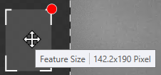 Note: For more information, refer to the Blue Locate Tool – Feature Size topic.
 -
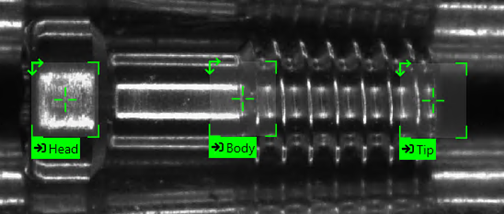
Within the ROI, while hovering over the image, the mouse-cursor will have a cross-hairs icon which is used to place the feature label of the Blue tool. Click on a feature to label it.
Note: For more information, refer to the Blue Locate Tool – Labels and Markings and Blue Locate Tool – Apply Feature Label Graphics – Tips and Shortcuts topics. -
The feature label will have a default character of 0. Enter in a meaningful character (A-Z, 0-9, up to 140 characters) to identify the feature. For identical features, you can use the same identifier.
If there is more than one feature that you want to find in the image, identify and label each feature.
-
Create a model out of the labeled features:
-
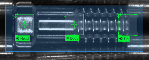
Select the labeled features that will compose the nodes of the model. To create a node model of multiple features, hold down the Shift key while selecting the labeled features, or hold down the Shift key and drag your mouse over the desired features.
-
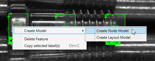
After selecting the labeled features, right-click on the View and from the menu, click on Create Model and select Create Node Model.
-
This will automatically use the selected features and area as the nodes for the model, based on the input image, and open the Model Editor dialog.
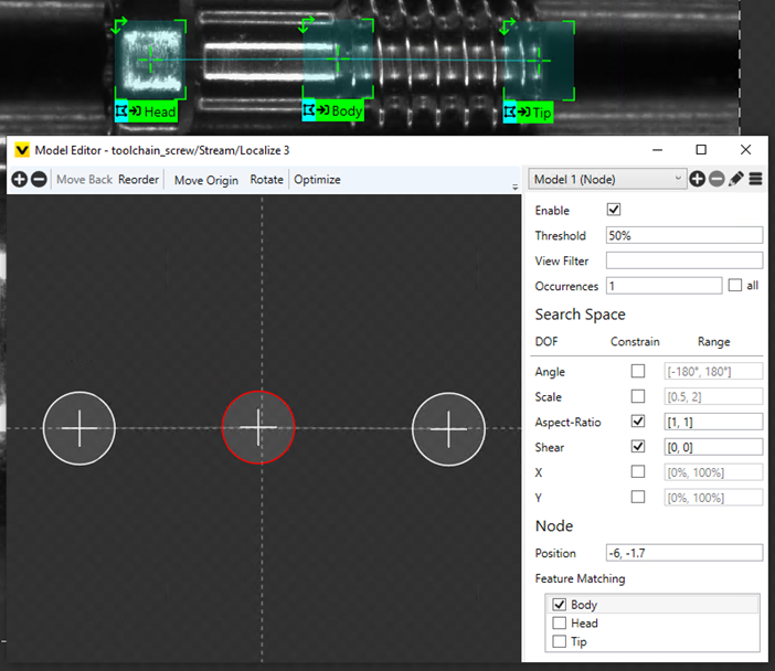 Note: See the Node Model Editor Parameters for more information about configuring the parameters of the node model.
 - With the node model created, you can now label the rest of the images/views based on the node model.
-
The node model will be based on the last labeled feature when you generated the node model. Place this label on the feature, and the tool will automatically generate the node model.
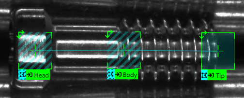
-
The other nodes will indicate that they are potential parts of the node model. Select each feature to label each instance of the node.
Note: For more information about the color codes of the labels, see the Blue Locate Tool – Labels and Marking Legend topic.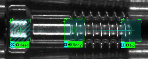
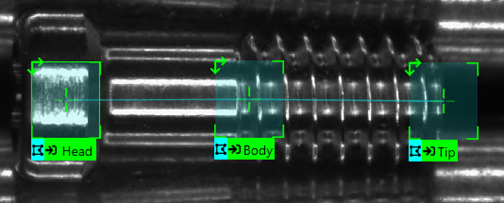
- Label the rest of the images/views based on the previous two steps.
-
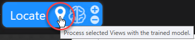
Press the Process icon of the tool to apply the model to all of the images.
-
-
Once you have applied the node model to several of the images, press the Brain icon to train the tool.
Tip: In addition to the following tips, consider using the bootstrap method of labeling your images. "Bootstrap" labeling refers to the process of beginning your labeling process by just labeling a small sample size of your images, then training the tool, and reviewing the results by accepting views with correct markings to convert them into labels, and removing incorrect markings and replacing them with correct labels. You can speed up this process further by dividing images into multiple views and only labeling a single view. In addition, you can also temporarily reduce the Epoch Count parameter (one of the Training Tool Parameters), which will make the training time shorter. - After training, review the results by going through all of the images and determining whether or not the tool correctly marked the features and generated the appropriate model in the image.
-
Go through all of the images and determine whether or not the tool correctly marked the features in the image.
- If the tool has correctly marked the features and the model, right-click the image and select Accept View.
-
If the tool has incorrectly marked the features or model, failed to identify a present feature or generated mismatches, do the following:
Note: If the tool has placed one or more mismatched features (indicated by an orange outline), refer to the Mismatches topic.- Right-click the image and select Accept View.
- Right-click the image again and select Clear Markings and Labels.
-
Manually re-label the features in the image based on steps E through F above.
- If you encountered the scenario in (A.), you are ready to use the tool. If you encountered the scenario in (B.), you will need to retrain the tool and repeat the previous two steps.