Create Models
Model
A model in Blue Locate and Blue Read is a group of features that appears following a certain pattern. This pattern can be geometrical position (Node Model) or the number of character features that appear glued to each other (String Model in Blue Read). For example, a node model can be a group of 5 features, which form a star formation in terms of their relative geometrical positions. Models are just like labels, so you can consider them a "group label." By creating a model, you define a label consisting of multiple features that appear following a specific pattern in views. Like individual feature labels, the model should be defined and created (labeled) on each view. But the model in Blue Locate and Blue Read is not a neural network and it is not trainable. The model can/cannot be correctly found on each view after processing, and so there can be matched/mismatched models in views.
The Blue Locate tool can generate a model based on the geometric relationship of features (Node Model) or areas of the image (Layout Model).
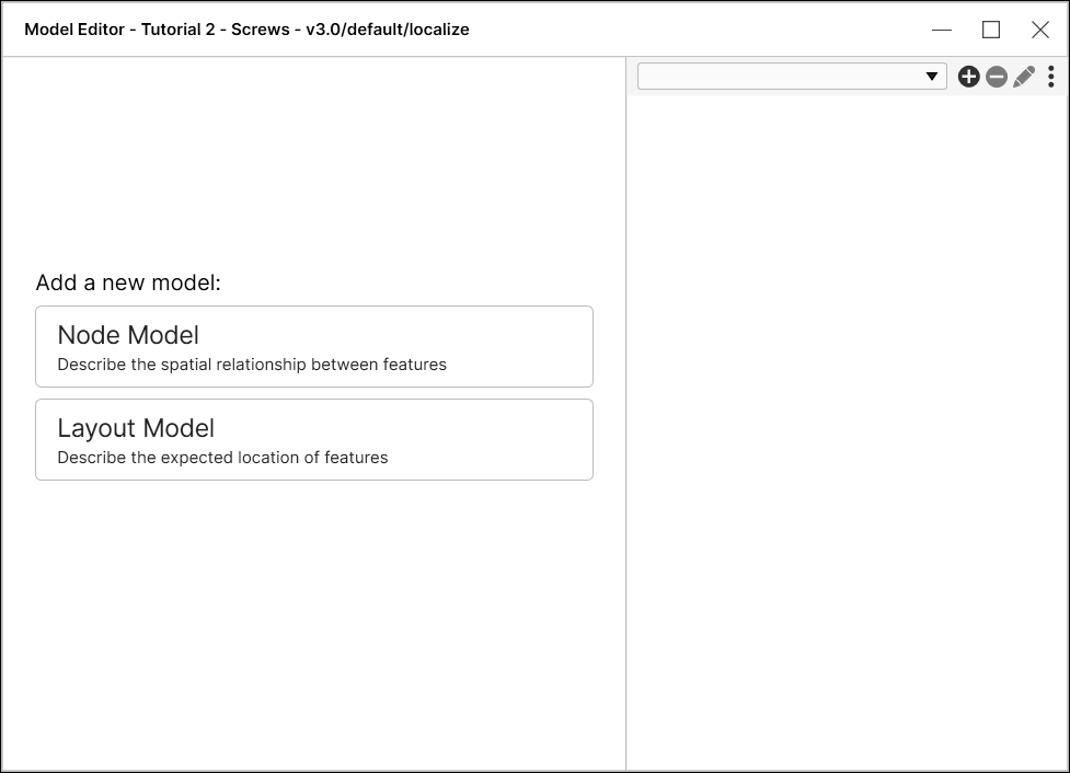
- The node model is used to identify features based on their geometrical position.
- The layout model is used to identify whether or not one or more feature is present in a specific area of the image.
Blue Locate Node Model
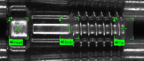
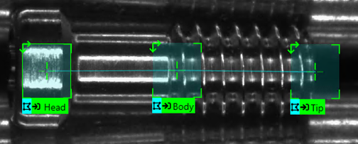
Node models are a used to group features together that appear in a similar geometrical position, and a node model provides a transform that can be consumed by downstream tools to adjust the orientation of Views.
The node model has its own properties relating to the number of features that can be found (nodes), the identifier of each node that can be found, as well as the minimum distances and angle range that the model can exist in. Models can also be created and detected after training the tool.
Each node of the node model also has some of its own information, such as angle, position in the node model, and what the valid features are for that node.
How to Create a Node Model
Once features have been labeled, a node model can be generated.
-
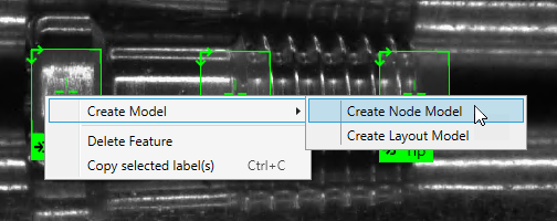
Select the labeled features that will compose the nodes of the model. To create a node model of multiple features, hold down the Shift key while selecting the labeled features, or hold down the Shift key and drag your mouse over the desired features.
-
After selecting the labeled features, right-click on the View and from the menu, click on Create Model and select Create Node Model.
-
This will automatically use the selected features and area as the nodes for the model, based on the input image, and open the Model Editor dialog.
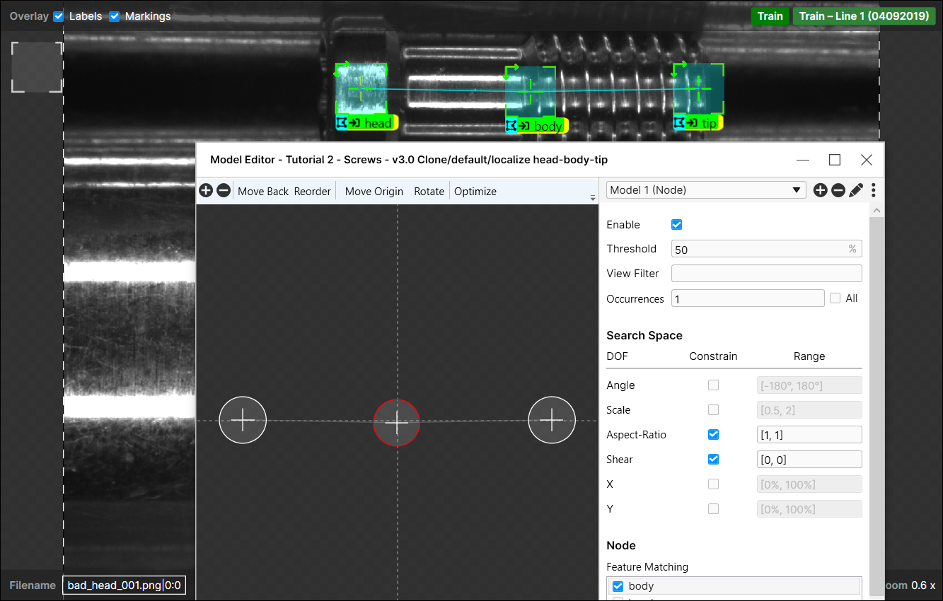 Note: See the Node Model Editor for more information about configuring the parameters of the node model.
 - With the node model created, you can now label the rest of the images/views based on the node model.
-
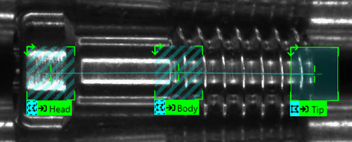
The node model will be based on the last labeled feature when you generated the node model. Place this label on the feature, and the tool will automatically generate the node model.
-
The other nodes will indicate that they are potential parts of the node model. Select each feature to label each instance of the node.
Note: For more information about the color codes of the labels, see the Review Markings.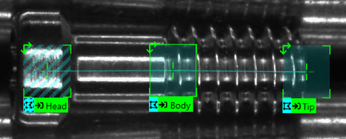
- Label the rest of the images/views based on the previous two steps.
-
Press the Process icon of the tool to apply the model to all of the images.
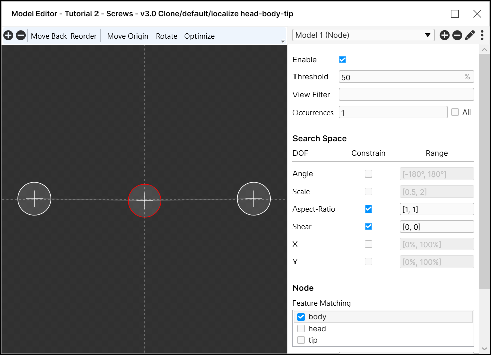
Node Model Editor
Optimize
| Parameter | Description |
|---|---|
|
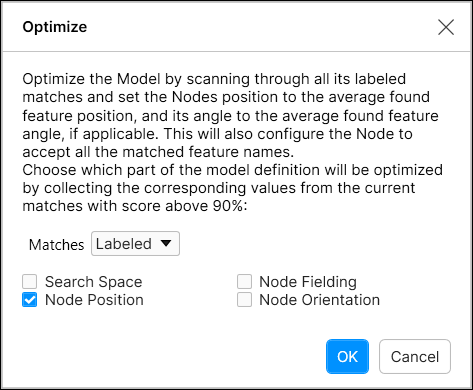
Optimize |
The Optimize option uses the results (markings) of the last run of the tool and optimizes the geometry and fielding of the nodes in the model (you can select which to use with the checkboxes) based on the markings. Generally, when you create a node model, you specify the geometry from the nodes found in one image. The Optimize option lets you adjust the node positions based on a several images. |
|
Enable |
Specifies whether or not the model should be active. |
|
Threshold |
Specifies the lowest score allowed to be a match for the model. |
|
View Filter |
Specifies a filter to determine which views the model will be applied to. When used, the model will be selectively enabled for views that satisfy the filter. |
|
Occurrences |
Specifies how many instances of a model should be detected. Enable the all checkbox, and the tool will detect all model instances. |
|
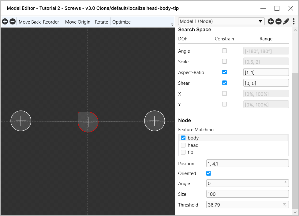
Search Space |
|
|
Constrain |
When enabled, the Constrain checkbox limits model matches to the Range specified for the Degree of Freedom (DOF) parameter. If disabled, models will be matched regardless of the Range specified for the DOF parameter, and the Range values will be grayed out to indicate that they are not active. |
|
Angle |
Specifies the possible orientations the model may exhibit. |
|
Scale |
Specifies the amount of deviation in the overall model size, and in the deviation of inter-node spacing, that will be allowed for a match. For example, a value of [0.8, 1.2] would specify that the overall size of the model must be between 80% and 120% of the nominal size, and the spacing between any two nodes in the model must also be between 80% and 120% of the nominal spacing. |
|
Aspect-Ratio |
Specifies the amount of deviation in the overall model aspect ratio, and in the deviation of inter-node ratios, that will be allowed for a match. |
|
Shear |
Specifies the amount of deviation in the shear mapping of the model, and in the deviation of inter-node shearing, that will be allowed for a match. |
|
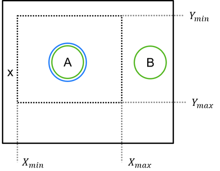
X |
The X and Y parameters specify the search region within the View, expressed in percentage terms. For example, to search only the upper-left quadrant of a View, you would specify [0%, 50%] for both X and Y. With these settings, only model matches where all of the nodes lie within the specified region will be returned. In the example shown below, A is matched, but B is outside of the X and Y range, so it is not matched with A to form the A-B model.
|
|
Y |
|
| Node | |
|
Position |
Specifies the expected pixel position of the selected node. |
|
Feature Matching |
Specifies the labeled feature that should be matched at the selected node position. |
| Oriented |
Specifies whether this node is oriented or not. If this parameter is enabled, the Angle parameter is activated below and only the character feature with this specific angle will be matched for the selected node. |
| Angle | Specifies the orientation of this node in degrees. This parameter is only activated when the Orientation parameter is enabled. |
| Size | Specifies the size of this node. |
| Threshold | Specifies the minimum feature score that should be matched for the selected node. |
Blue Locate Layout Model
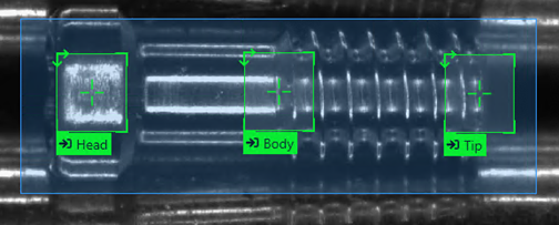
The Blue Locate tool also gives you the option of creating a region-based model, where you can instruct the tool to search specific areas of the image for specified features. The layout model can be used to do the following:
- Check for the presence of a feature within one or more regions.
- Verify that the correct feature is in the region, along with the number of instances of that feature within the region.
- Provide a Region of Interest (ROI) for a downstream tool.
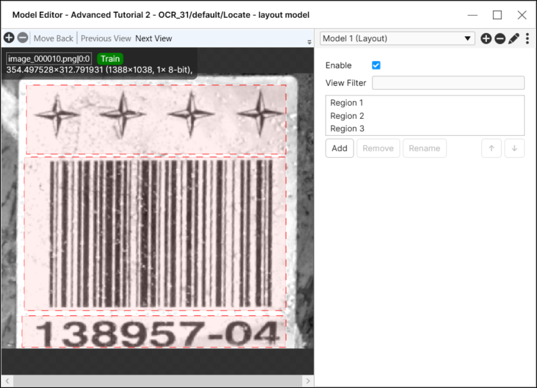
How to Create a Layout Model
Once features have been labeled, a layout model can be created. There are two different methods to create a layout model:
- The right-click menu, Create Model option
- The Tool menu, Edit Models option
One limitation of the layout model interface is that a given region may specify which feature types are valid as well as the total number of features (Feature Count) that are required for the region to be valid. More complex types of validation expressions are not supported (for example, a single region that requires one instance of FeatureA, three instances of FeatureB and two instances of FeatureC).
To implement more complex validation expressions, you can "stack" regions by creating multiple regions with the same location and dimensions, but different validation criteria for each region. For example, Region1 would have FeatureA selected, and one instance of FeatureA; Region2 would have FeatureB selected, and three instances of FeatureB; and Region3 would have FeatureC selected, and two instances of FeatureC.
In order for the model to pass, all of the regions must pass.
Create a Layout Model – Right-click Menu Option
-
Select the features that you want included in your layout model, right-click above one of the features and select Create Layout Model.
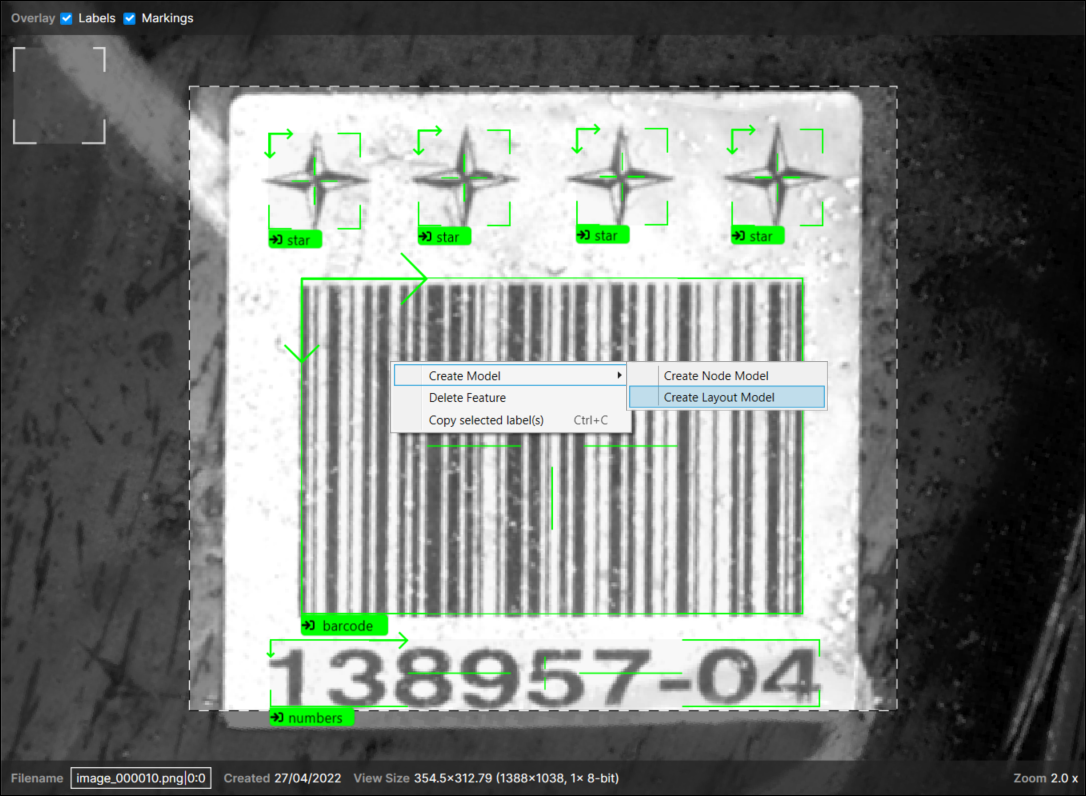
-
The tool will automatically generate a layout model.
-
Each feature will have a corresponding layout region (the name corresponds to the feature), with the feature automatically selected for the region. Modify the regions and selected features as desired.
-
Press the Process icon of the tool to apply the model to all of the images.
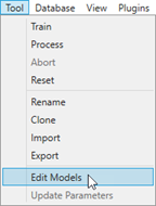
Create a Layout Model – Edit Models Option
-
Label the desired features that should be in your layout model.
-
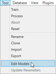
From the Tool menu, select Edit Models.
-
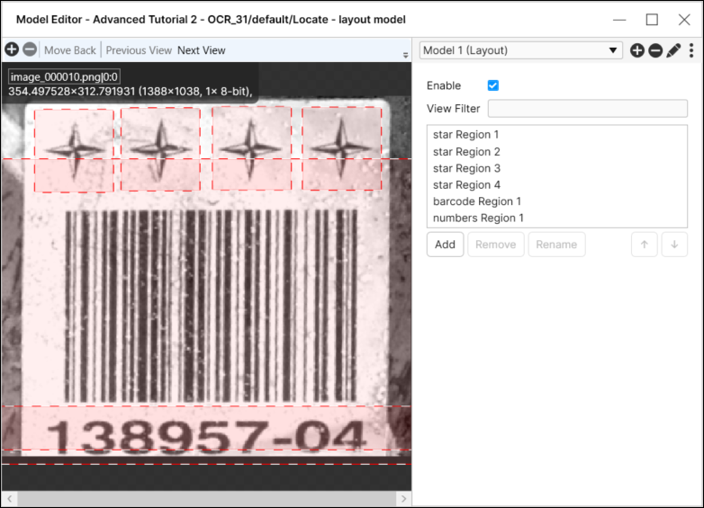
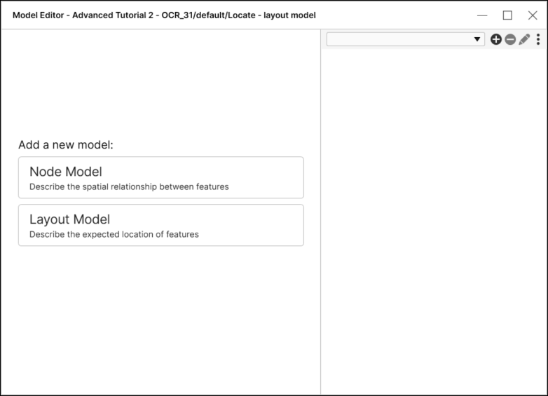
In the Model Editor dialog, select Layout Model.
-
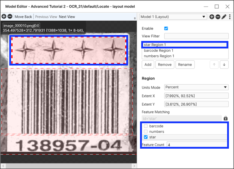
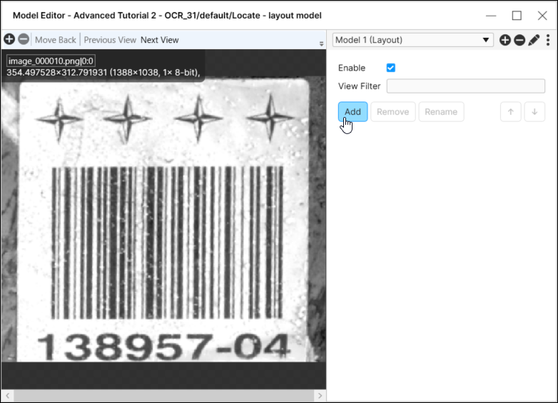
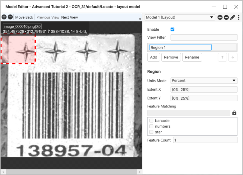
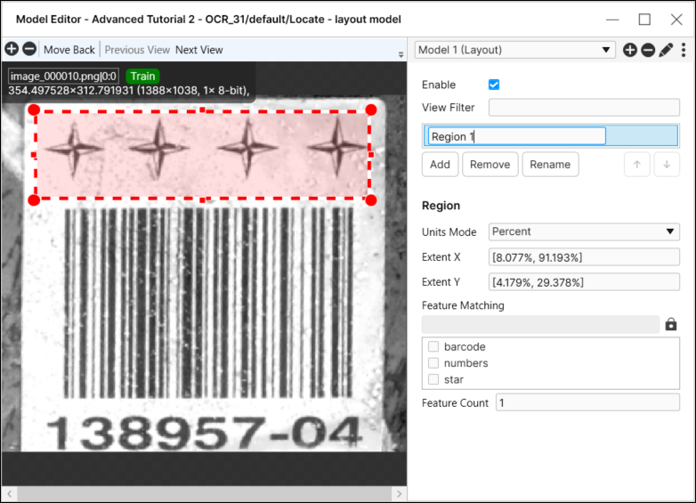
This will launch the layout model editor, where you can press the Add button to configure a region of interest that will define where to search for one or more features.
-
Configure the region of interest over the desired area of the image.
-
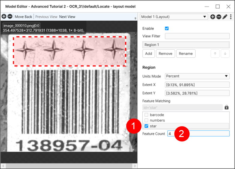
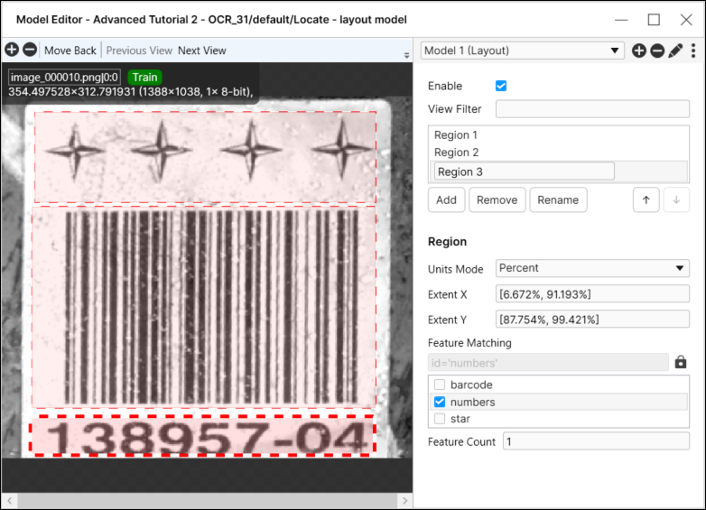
Select the region, and then select the feature(s) in the Feature Matching selector menu, and in the Feature Count field, set the number of instances for all of the features (in other words, the sum) within the region.
-
You can repeat steps 3 through 5 for each of the regions that should compose the model.
-
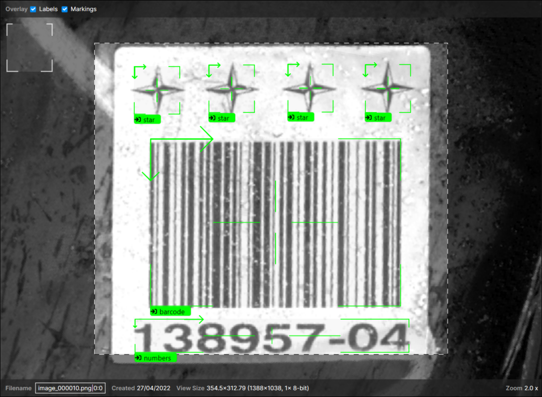
After closing the layout model (press the X button in the upper-right corner of the dialog), you will get feedback by the tool in the image/view.
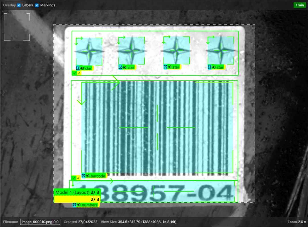
The check marks in the lower-left corner indicate if the region passed. If the features were not found, there will be an X instead of a check mark.
-
Press the Process icon of the tool to apply the model to all of the images.
Layout Model Editor

| Parameter | Description |
|---|---|
|
Enable |
Specifies whether or not the model should be active. |
|
View Filter |
Specifies a filter to determine which views the model will be applied to. When used, the model will be selectively enabled for views that satisfy the filter. |
|
Region Box |
Displays the list of regions within the model |
| Region | |
|
Units Mode |
Specifies the dimensions of the selected region either as a percentage of the image/view, or in pixels. |
|
Extent X |
Specifies the width of the selected region, measured from the upper-left corner of the image/view. |
|
Extent Y |
Specifies the height of the selected region, measured from the upper-left corner of the image/view. |
|
Feature Matching |
Specifies which features should be assigned to the region. Multiple features can be selected. |
|
Feature Count |
Specifies the sum of the features that are valid for the region. For example, if you have two instances of DualTransistors and one IntegratedCircuit, you would set the Feature Count to 3. |
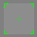
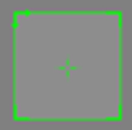
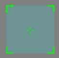
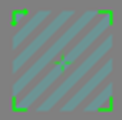
Feature Label Graphics with Model Defined
This topic provides an overview of the feature label graphic, the states of the labels when one or more models were created.
| Feature Label, Not in a Model | Feature Label, in a Model | Feature Assumed to be in a Model | |
|---|---|---|---|
|
Label |
|
|
|

| Unselected | Selected | In a model | Assumed to be in a model | |
|---|---|---|---|---|
|
Label feature graphic |
|
|
|
|
Import/Export Model
Both the Layout Model and Node Model types support being exported and imported into other Blue Locate tools. This allows you to quickly create new models, based on an existing model by importing a previously created model.
When exporting a model, VisionPro Deep Learning will package all of the information about the model into a model archive file. Then, when importing a model archive file into another Locate tool, a duplicate of the model is created.
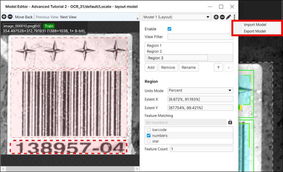
Import a Model: Use the Model Editor
When a model archive file has been created by exporting a model, the exported model can be imported into another Blue Locate tool using the Model Editor.
-
From the Tool menu, select Edit Models.
-
From the sandwich menu in the right-corner of the Model Editor dialog, select Export Model.
-
This launches an Open dialog, where you can navigate to the desired directory and load the model archive file.
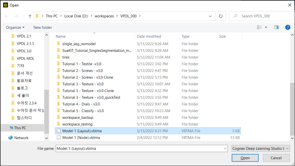
-
The model will then be loaded.
- Adjust the model to match the features in the tool the model was imported into.
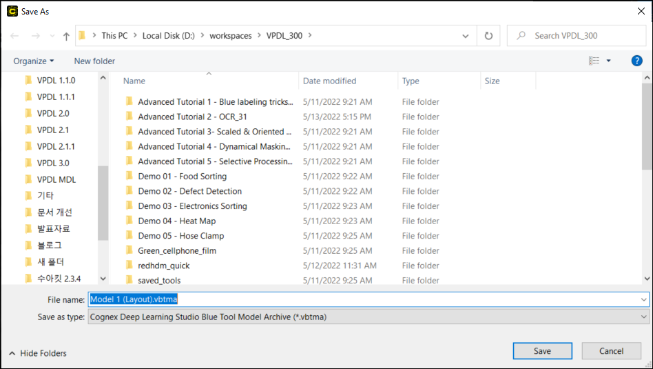
Export a Model: Use the Model Editor
With a model created in a Blue Locate tool, you can use the Model Editor to export a model for use by another tool.
-
From the sandwich menu in the right-corner of the Model Editor dialog, select Export Model.
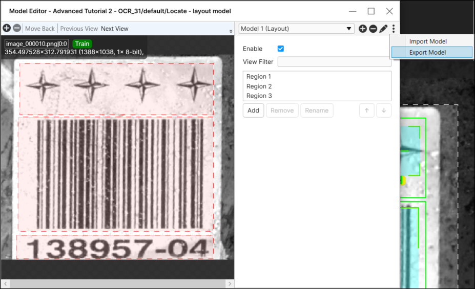
-
This launches a Save As dialog, where you can navigate to a desired directory and save the model archive file.