 9-Point Calibration Type
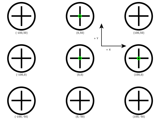
The 9-Point calibration option is useful in robotic applications where you want to create the correct coordinate space for the robot. This calibration option relies on a circular target, as illustrated below. Ideally, the calibration plate should be composed of nine evenly spaced targets, in a grid pattern. The horizontal and vertical distance between targets should be known prior to beginning the calibration process.
- The target in the center of the nine targets will be considered the origin (0,0) in the robot coordinate system.
- The spacing between horizontal targets must be consistent and equal, and that applies to the spacing between the vertical targets, as well. However, the spacing between the horizontal and vertical targets does not need to be equal.
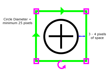
- Each target must have a minimum circle diameter of 25 pixels.

Before beginning the calibration process, capture an image of the calibration plate, which contains the nine evenly spaced targets.
- Select 9-Point from the Calibration Type drop-down menu.
-
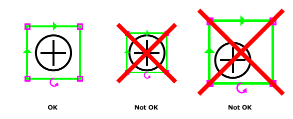
Press the Edit Model button, and configure the region so that it encloses the middle target, and then press the OK button. When configuring the region around the target, ensure that there is at least 3 to 4 pixels of blank pixels between the outer edge of the circle and the region. Also attempt to center the region over the target as much as possible.
-
After configuring the model, EasyBuilder will automatically detect all of the targets in the image, and will display a green cross over the detected targets.
Note: If the target's fiducial is detected, but the circle surrounding the fiducial is not detected, a red cross will be displayed. Either re-train the model or acquire a new image to resolve the issue. - From the Units drop-down menu, select the real world units (Microns, Millimeters, Centimeters or Inches).
- In the X-Dimension field, enter the real world measurement of the horizontal distance between two targets in the same row (measured from the center of each target).
- In the Y-Dimension field, enter the real world measurement of the vertical distance between two targets in the same column (measured from the center of each target).
- Press the Calibrate button to finalize the calibration process. The results of Location and Inspection Tools will now appear in real-world units.

