 Image Settings
Trigger
The Trigger controls, Type, Delay and Interval, allow you to customize how and when an image is acquired and the inspection will be performed.
The drop-down menu allows you to specify the source of the image acquisition trigger when the In-Sight vision sensor is Online.
| Camera | Enables image acquisition on a rising edge sensed at the vision system's dedicated acquisition trigger input. |
|
Continuous |
Enables "free running" (as fast as possible) image acquisitions. |
| Manual |
Enables image acquisition when pressing F5. Note: You can manually trigger the sensor by pressing the TRG button on the vision sensor.
|
| Industrial Ethernet |
Enables triggering from an Industrial Ethernet protocol, such as EtherNet/IP, PROFINET, SLMP Scanner, or CC-Link IE Field Basic. |
The control allows you to specify a delay, in milliseconds (0 to 10,000), between the time the trigger is received and the time the In-Sight vision sensor begins the acquisition. The trigger Type must be set to Camera.
- The Delay is accurate to one millisecond, plus or minus the maximum line exposure time, which is 64 microseconds.
- If Acquisition Start is the specified Signal Type in the Inputs/Outputs step, these outputs will be delayed by the specified time.
The control allows you to specify an interval, in milliseconds (0 to 10,000; default is 0), between acquisitions when the Type control is set to Continuous.
Focus (In-Sight 2000 Vision Sensors with Autofocus Only)
The Focus tab is used to control the focus position of the lens on supported In-Sight 2000 series vision sensors with the Autofocus feature, by either automatically focusing the lens or moving the lens to a specific focus position.
Specifies the region of the image that will be used when automatically focusing the lens. Press the Autofocus Region button to configure the region.
Automatically focuses the lens, to maximize image sharpness within the region.
- Unchecked (= default): The current Focus Distance (%) will be saved with the job.
- Checked: The vision sensor will automatically focus the lens when the job is loaded.
Manually adjusts the focus position (0 - 100%. Default: 6.2mm lens = 66%, 16mm lens = 69.2%). When attempting to focus on an object placed near the vision sensor, move the handle to the left (towards 0%). When attempting to focus on an object placed far from the vision sensor, move the handle to the right (towards 100%). You can move the handle regardless of the Live Video mode status.
Lighting
Automatically determine the exposure after each acquisition. This option helps to compensate for inconsistent lighting conditions, such as reflections from shiny metal surfaces, variable shadows and background lighting changes. Auto Exposure is disabled by default.
Sets a fixed exposure value to use for every image acquisition. Manual Exposure is enabled by default. To disable, check Auto Exposure.
Allows you to specify a desired brightness level (0 - 100; default = 50) by adjusting the handle or by entering a value in the corresponding edit box. The value is a percentage of the pixels in the Exposure Region that are allowed to be saturated (i.e. white).
The Exposure control determines the duration of the exposure when an image acquired (0.000 - 1000.000; default = 0.250). The higher the exposure value, the brighter the acquired image. This control is disabled when Auto Exposure is selected.
Allows you to specify the effective intensity of the LEDs in percentage [(0 to 100); default = 70; OFF = 0] by adjusting the handle or by entering a value in the corresponding edit box. The light intensity will be saved with the job.
The blue background shows the maximum light intensity value available for the current settings. The maximum light intensity value varies depending on other image settings, such as Target Image Brightness, Exposure, Image Area Height or Image Magnification Mode.
Defines the Region to use when automatically calculating the exposure.
- Click the Exposure Region button.
- Position the region around the image area that the sensor will use to determine the automatic exposure to use for the next acquired image.
- Click the OK button.
The exposure will now be calculated automatically based on the brightness of the image area within the Exposure Region. For example, if the image area within the Exposure Region is brighter than the rest of the image, then the next acquired image will be darker.
| Define Exposure Region | Next Acquired Image |
|---|---|
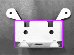
|
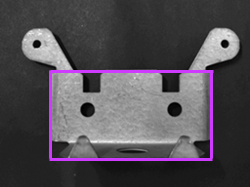
|
Automatically optimizes the exposure value. The same exposure value will be used for each subsequent image acquisition.
On (Exposure) enables the ring light to be ON only for the duration of the exposure (default). When Disabled (Off), the light will be powered off and the sensor will be dependent on ambient (room) lighting.
White Balance (In-Sight 2000 Color Vision Sensors only)
Removes color casts in a color image by calculating the image's red, green and blue (RGB) values and correcting them. As a result, items that are white in the real world, for example, will appear white in the image.
When creating a new job, the most recently performed white balance will be in effect. The white balance setting is saved with the job, and will be restored when the job is loaded.
- The white balance setting must be configured while using Manual Exposure.
-
To ensure the most accurate color reproduction in the image, white balancing is recommended after making large adjustments to Light Intensity.
-
Focus the In-Sight vision sensor on a flat test object, such as a piece of white matte paper, and adjust the Lighting controls to ensure that the image is not overexposed.
-
Click White Balance Region, and enclose a region of the image containing only light pixels, and no "hot spots".
Note: Click Reset to Default Region to reset to include the entire image. - Click Set White Balance. All subsequent image acquisition will now use this setting.
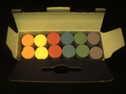
|

|
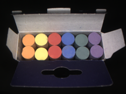
|
| Image Before White Balancing | White Balanced | Image After White Balancing |
Image
Defines the number of image rows to acquire to reduce image acquisition time when the area of interest is always limited to the same band of rows within the image. You can define the values by moving the left (Start Row) and right (End Row) handles or by entering values in the corresponding edit boxes.
| In-Sight Model | Resolution | Start Row value | End Row value |
|---|---|---|---|
|
2000-110 |
640 x 480 | 0 - 479 (default = 0) | 0 - 479 (default = 479) |
|
2000-120/120C |
640 x 480 | 0 - 479 (default = 0) | 0 - 479 (default = 479) |
| 2000-130/130C1 2000-230/230C1 |
640 x 480 (default) | 0 - 479 (default = 0) | 0 - 479 (default = 479) |
| 800 x 600 | 0 - 599 (default = 0) | 0 - 599 (default = 599) | |
| 2000-23M1 | 640 x 480 | 0 - 479 (default = 0) | 0 - 479 (default = 479) |
| 800 x 600 (default) | 0 - 599 (default = 0) | 0 - 599 (default = 599) | |
| 2001-230/230C1
|
640 x 480 | 0 - 479 (default = 0) | 0 - 479 (default = 479) |
| 800 x 600 | 0 - 599 (default = 0) | 0 - 599 (default = 599) | |
| 1280 x 960 (default) | 0 - 959 (default = 0) | 0 - 959 (default = 959) | |
| 1The resolution can be configured in the Image Settings dialog. | |||
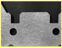
Enables Image Magnification Mode. When enabled, the FOV is reduced by 50%, while the optical resolution is increased by 200%.
| In-Sight Model | Resolution | Image Magnification Mode |
|---|---|---|
| 2000-110 |
640 x 480 | Not supported |
| 2000-120/120C |
640 x 480 | Can be enabled and disabled |
|
2000-130/130C1 2000-230/230C1 |
640 x 480 (default) | Can be enabled and disabled |
| 800 x 600 | Always enabled | |
| 2000-23M1 | 640 x 480 | Can be enabled and disabled |
| 800 x 600 (default) | Always enabled | |
| 2001-230/230C1 | 640 x 480 | Can be enabled and disabled |
| 800 x 600 | Always enabled | |
| 1280 x 960 (default) | Always enabled | |
| 1The resolution can be configured in the Image Settings dialog. | ||
|
Image Magnification Mode Disabled |
Image Magnification Mode Enabled |
|
|
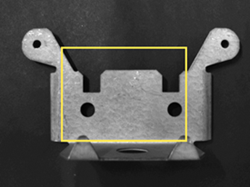
Allows you to convert or calibrate the Inspection tools from pixels into real world units of measurement. There are two options: Field of View or Import.
- The Field of View option is not available on the In-Sight 2000-110 and 2000-120/120C vision sensors.
- The Import option is only available on the In-Sight 2000-23M vision sensor.
Converts the results of the Measurement tools from pixels into real world units of measurement (millimeter, centimeters and/or inches).
|
| Field of View (Width) = 640 pixels / 125 millimeters |
- Select Field of View (Width) from the Calibration Type drop-down menu.
- Select the real world unit of measurement to use (Millimeters, Centimeters or Inches) from the drop-down menu. Pixels is selected by default and the value cannot be changed.
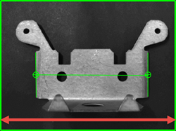
- Measure the width of the Field of View as accurately as possible in the selected unit of measurement, then enter the measured value.
-
The conversion of the measurement result will be applied immediately. For example, if the Field of View (Width) is set to 125 millimeters and the measured distance between the two edges is 490 pixels, the measurement result will be returned as 95.703 mm.
Note:- Followings are the formula and the actual calculation used in the example:
- Field of View (real world units) / Field of View (pixels) * Measurement (pixels) = Results (real world units)
- 125/640*490 = 95.703mm
- Followings are the formula and the actual calculation used in the example:
The Import Calibration Type is used to load a calibration file that has been created by an N Point Calibration Tool, and exported to the In-Sight vision sensor's local file system. The imported calibration file automatically calibrates the current job as soon as it has been loaded.
The N Point Calibration Tool creates a 2D transformation to convert between pixel and real-world coordinate systems. The tool performs the following transformations:
- Translation in two dimensions (using 2 or more point pairs).
- Rotation about three axes (using 4 or more point pairs).
- Scale in two dimensions (using 2 or more point pairs).
- Perspective distortion (using 4 or more point pairs).
- Parallelogramming or skewing (using 4 or more point pairs).
How to use
- Select Import from the Calibration Type drop-down menu.
- EasyBuilder will automatically examine your job for any calibration files generated by an N Point Calibration Tool, and load the calibration file. If you have created more than one calibration file, select your desired file from the File Name drop-down menu.
- From the Units drop-down menu, select the real-world measurement units that define the calibration: Microns, Millimeters (default), Centimeters or Inches.
- The calibration will be applied as soon as this option is selected and the values are configured.