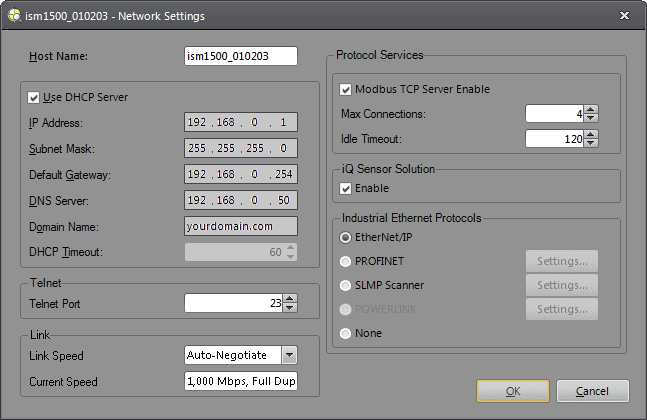
Network Settings Dialog
The Network Settings dialog configures the active In-Sight vision system to communicate on a TCP/IP network.
- If you choose not to restart an In-Sight vision system after modifying its network settings, In-Sight Explorer will not reflect the modifications until the vision system has been rebooted, despite the fact that the Network Settings dialog reports the new configuration.
- In-Sight emulators inherit their network settings from Windows; these settings cannot be changed within In-Sight Explorer. To modify an emulator's network settings, open the network applet in the Windows Control Panel and make the desired change.
- In-Sight automatically allocates EtherNet/IP multicast addresses from the IPv4 Organization Local Scope: 239.192.0.0/14.
Network Settings Dialog Controls
To display the Network Settings dialog, click Network Settings from the Sensor menu.
When connected to an In-Sight vision system/sensor running firmware version 5.8.0 or later, the following options are available.

When connected to an In-Sight vision system/sensor running firmware version 5.7.0 or later, the following options are available:

When connected to an In-Sight vision system/sensor running firmware version 5.3.0 or later, the following options are available:

When connected to an In-Sight vision system running firmware version 5.2.x or earlier, the following options are available:
Host Name
Specifies the name of the networked In-Sight device. Each device has its host name set automatically the first time it boots. You can change the host name by entering a new name into the field. Host names can contain a maximum of 63 characters. Valid characters for the host name are A–Z (upper and lowercase), 0 - 9, hyphen ('-'), colon (:), period ('.') and underscore ('_').
The default naming convention is as follows: "is" for "In-Sight", the model number, an underscore and the last 6 characters of the vision system's unique Media Access Control (MAC) address.
The MAC
address is a hardware address that identifies a specific node of a network. Every
In-Sight vision system has a unique MAC address assigned to it, which cannot
be changed. For example, 00-d0-24-01-02-03. To locate the MAC address of an In-Sight vision system, look at the
serial number label affixed to the vision system. Alternately, you can open the About In-Sight Explorer dialog.
For example, the host name of an In-Sight 7802 vision system with the MAC address of 00-d0-24-01-02-03 is "is7802_010203". The host name can be changed by entering a new name into the field.
If the local system is a networked PC running an In-Sight emulator, the host name is automatically inherited from the computer's name as defined in the Windows operating system.
Use DHCP Server
Specifies that the In-Sight vision system will be
configured dynamically
by the DHCP server on startup.
- IP Address: Assigns a unique identifier for each In-Sight vision system on the network, which must be consistent with the IP address-numbering scheme of the local network.
-
Subnet Mask: Defines which part of the IP address refers to the network and which part refers to the host. The network part of the IP address is the same for all hosts on the same subnet, and the remainder is unique to each host.
There are three classes of subnet masks. The class of a particular subnet on a network is defined by the number of bits used to represent the network and host address portions in the IP address, as in the table below:
Class Subnet Mask Network Address Host Address A
255.0.0.0
8 bit
24 bit
B
255.255.0.0
16 bit
16 bit
C
255.255.255.0
24 bit
8 bit
For example, consider a networked In-Sight host system with the IP address 192.168.0.1. If the first three numbers (192.168.0) identify the 24-bit network address, and the last number (1) is the 8-bit address for the In-Sight host on the network, then the subnet mask for this host is 255.255.255.0.
- Default Gateway: Specifies the IP address of the gateway host, if available on the network. The gateway host is responsible for relaying data between hosts on different networks. If an In-Sight device needs to communicate with a device on a different subnet, enter the address of the gateway device in the Default Gateway field. Otherwise, leave the field blank.
- DNS
Server: Specifies the IP address of the
host on the network providing DNS
resolution, if available.
- Domain Name:
Specifies the network domain
for the host network. Domain names can contain a maximum of 63 characters.
-
DHCP Timeout: Specifies the time (5 to 180 seconds; default = 60) an In-Sight vision system will wait for a DHCP server to respond with an available IP address, when the vision system is configured for DHCP. If the vision system times out, network communication will be suspended. The vision system will not attempt to connect to the network again until power is cycled on the vision system.
Tip: If the In-Sight vision system is not going to be connected to a network, specifying the minimum time of 5 seconds will reduce boot-up time of the vision system; the vision system must be configured for DHCP.
Link
-
Link Speed: Specifies the Ethernet speed and duplex mode between the vision system and the network device.
CAUTION: If the network device is not configured to support the specified link speed, the vision system will not be reachable; configure the network device's Ethernet settings to match that of the vision system.- Auto-Negotiate (default): The vision system and network device communicate to choose the fastest Ethernet speed and duplex mode supported by both devices.
- 10 Mbps Half Duplex: Ethernet speed is fixed to 10 megabits per second and data can only be sent or received at a given time.
- 10 Mbps Full Duplex: Ethernet speed is fixed to 10 megabits per second and data can be sent and received at a given time.
- 100 Mbps Half Duplex: Ethernet speed is fixed to 100 megabits per second and data can only be sent or received at a given time.
- 100 Mbps Full Duplex: Ethernet speed is fixed to 100 megabits per second and data can be sent and received at a given time.
-
1000 Mbps Full Duplex: Ethernet speed is fixed to 1000 megabits per second and data can be sent and received at a given time.
Note: The 1000 Mbps Full Duplex option is only available for vision systems that support 1000 Mbps Ethernet speeds. For In-Sight 5600 series vision systems, it is only available on models with 128MB non-volatile flash memory or higher.
- Current Speed: Displays the vision system's current Ethernet link speed and duplex mode (full or half).
Telnet
Specifies the vision system's telnet settings.
- Telnet Port: Assigns the telnet port on which the active In-Sight vision system (a TCP/IP server waiting for communication) listens for incoming requests from a remote device (a TCP/IP client that initiates communication). A valid port assignment is any unused number between 1 and 65535, excluding ports reserved for In-Sight communications. For more information, see In-Sight Ports.
Industrial Ethernet Protocols
Enables or disables specific Ethernet protocols on In-Sight vision systems. When using an Industrial Ethernet protocol, set Robots to None.
- If you are using EasyBuilder, you need to add and configure the Industrial Ethernet Device settings in the Communication application step. Otherwise, the Format Output Buffer settings are not configured and you will not get any result data. For more information, refer to the Device Setup topic in the EasyBuilder Help (Communication > Device Setup).
- If you are using Spreadsheet, you need to enable the Industrial Ethernet protocol using this dialog. When selected protocol is PROFINET, SLMP Scanner, POWERLINK or Modbus TCP Server, you also need to configure the settings using the Settings button.
- The EtherNet/IP, PROFINET, SLMP Scanner, POWERLINK and Modbus TCP Server protocols are mutually exclusive; therefore, protocols cannot be enabled at the same time.
-
EtherNet/IP: Enables the EtherNet/IP service on the vision system. Once selected, enables the Settings button to the right of the option, which launches the EtherNet/IP Settings dialog to configure the Enable User Data Bypass setting. Check the Enable User Data Bypass checkbox to bypass the cached data and read the raw user data directly. By default, this setting is disabled.
Note: The Settings button next to the EtherNet/IP option is only available on In-Sight vision systems running In-Sight firmware 5.4.0 and later. -
PROFINET: Enables the PROFINET service on the vision system. Once selected, enables the Settings button to the right of the option, which launches the PROFINET Settings dialog to configure settings.
Note: POWERLINK is only supported by In-Sight 70xx - 74xx series vision systems running In-Sight firmware version 4.7.2 or later, and In-Sight Explorer software version 4.7.2 or later. It is not supported with firmware version 5.1.0 or later. - SLMP Scanner: Enables the SLMP Scanner service on the vision system. Once selected, enables the Settings button to the right of the option, which launches the SLMP Scanner Settings dialog to configure settings.
- CC-Link IE Field Basic: Enables the CC-Link IE Field Basic protocol on the vision system. Once selected, enables the Settings button to the right of the option, which launches the CC-Link IE Field Basic Settings dialog to configure the User Data Bypass setting.
- POWERLINK: Enables the POWERLINK protocol on the vision system. Once selected, enables the Settings button to right of the option, which launches the POWERLINK Settings dialog to configure settings.
-
Modbus TCP Server: Enables the Modbus TCP Server service on the vision system. Once selected, enables the Settings button to the right of the option, which launches the Modbus TCP Server Settings dialog to configure settings.
Note: This option is only available on In-Sight vision systems running In-Sight firmware version 5.3.0 or later. - None: Disables the Industrial Ethernet protocol on the vision system.
-
Enable iQ Sensor Solution: Enables or disables the iQ Sensor Solution on In-Sight vision systems.
Note:- iQ Sensor Solution is only available on In-Sight vision systems using In-Sight firmware 4.x.x, or 5.7.4 or later.
- Do not change the Network settings simultaneously in iQSS (GXWorks) and the Network Settings dialog.
OPC UA
- Enable OPC UA Server: Enables or disables the In-Sight vision system/sensor to act as an OPC UA server. For more information, see OPC UA.
Modbus TCP Server Enable
-
Modbus TCP Server Enable: Enables or disables the In-Sight vision system to act as a Modbus/TCP server; multiple simultaneous connections are supported, as well as a configurable session idle timeout. When configured as a Modbus/TCP server, the vision system maintains a running count of the number of clients it will allow to connect. For each new established connection, the server subtracts from the maximum allowed connections until the count reaches zero, and any subsequent connection requests will be explicitly rejected. The server will only accept subsequent connection requests when the existing clients either explicitly close their connections or have their connections implicitly closed due to an idle timeout.
Note:- The Modbus TCP Server Enable checkbox, Max Connections and Idle Timeout controls in the Protocol Services group box are only available on In-Sight vision systems running 4.x.x firmware. If using In-Sight vision systems running firmware version 5.3.0 or later, see Modbus TCP Server in the Industrial Ethernet Protocols group box.
- When enabled, it is recommended that the maximum number of connection limits be set to 2x (two times) the number of Modbus/TCP connections that the application actually requires. This is done so that in the event of a power failure or a client reboot, all connections can be re-established without having to wait for the old connections to timeout.
- Max Connections: Specifies the maximum number of simultaneous connections the vision system will support. (1 to 6 connections; default = 4)
- Idle Timeout: Specifies the amount of time since the last issued Modbus/TCP request was received by the server from a client before that session is declared as idle. (0 to 3600 seconds; default = 120 seconds) The Modbus/TCP server checks all connected sessions every 500ms to determine if any session idle time limits have been reached. For all idle sessions, the Modbus/TCP server issues a socket close command and reclaims any resources allocated to the idle session.
- Enable User Data Bypass: Check this checkbox to bypass the cached data and read the raw user data directly. By default, this setting is disabled.
Robots
Enables or disables specific Robot controller communication on In-Sight vision systems. When using a Robot controller, set Industrial Ethernet Protocol to None.
- None: Disables the Robot controller communication on the vision system.
- Mitsubishi: Enables the Mitsubishi Robot controller communication on the vision system. Once selected, enables the Settings button to the right of the option, which launches the SLMP Scanner Settings dialog to configure settings.
Automatically Configure an In-Sight Vision System via DHCP
If your network uses a DHCP server
to assign IP addresses, select the Use
DHCP Server checkbox. The active In-Sight vision system is configured
dynamically
by the DHCP server on startup.
Optionally, a new host name and DHCP timeout can be assigned, but all other fields in the Network Settings dialog will be disabled. When a large number of vision systems are present, this setup is often preferred to entering configuration settings manually for every vision system. After initial setup, disabling DHCP on the vision system(s) and assigning a static IP address is strongly recommended.
If the Use DHCP Server checkbox is unchecked, then the network settings for the active In-Sight vision system must be configured manually.
Manually Configure an In-Sight Vision System for a Non-DHCP Network
-
Deselect the Use DHCP Server checkbox, if it is currently selected.
Note: If the In-Sight vision system previously had its network settings configured manually, those settings are automatically restored after you deselect the Use DHCP Server checkbox. - Enter an IP Address.
- Enter a Subnet Mask.
- Optionally, configure the Host Name, Default Gateway, DNS Server and Domain Name.
- Click OK.
- You will be prompted to cycle power on the vision system so that any configuration changes can take effect.