Red Analyze Focused Unsupervised
Overview of Red Analyze Architectures
The Red Analyze tool is used to inspect images, find defect pixels, and distinguish defective images from normal ones or vice versa. There are 2 types of architectures in Red Analyze Tool: Focused (Focused Supervised, Focused Unsupervised) and High Detail.
-
The Red Analyze Focused Supervised is used to segment specific regions such as defects or other areas of interest. Be it blowholes in cast metal or bruised vegetables on a conveyor; the Red Analyze tool in Supervised mode can identify all of these and many more problems simply by learning the varying appearance of the defect or target region. To train the Red Supervised tool, all you need to provide are images of the type of defective regions you are looking for.
-
The Red Analyze Focused Unsupervised is used to detect anomalies and aesthetic defects. Be it scratches on a decorated surface, incomplete or improper assemblies or even weaving problems in textiles; the Red Analyze tool can identify all of these and many more problems simply by learning the normal appearance of an object including its significant but tolerable variations. To train the Red Unsupervised tool, all you need to provide are images of good objects.
-
The Red Analyze High Detail is the reinforced version of Red Analyze Focused – Supervised in terms of segmentation performance but costs some drop in training and processing speed. Its higher performance compared to Red Analyze Focused – Supervised comes from its unique training architecture in segmentation tasks.
About Red Analyze Focused Unsupervised
With Red Analyze Focused Unsupervised, Red Analyze tool is taught the appearance of the good parts – and only the good parts (including any and all acceptable variations) – so that it finds anomalies from the learned, normal appearance. As such, the tool tries to find a compact description of the object to be inspected. The tool's ability to find anomalies, both in terms of selectivity and specificity, depends largely on the compactness of the model. If, for instance, the part comes in different types and different orientations, the compactness gets reduced, and ambiguities between part types and orientations may prevent the tool from finding certain anomalies.
When the Red Analyze tool is in Focused Unsupervised mode, the focus is on teaching the network what a good part looks like. Therefore, during training, the primary focus is on presenting good/passing images of your part (including any and all acceptable variations). However, it is also important to include labeled failing images during the testing and validation phases. This will allow you to determine how accurately the tool is detecting defects after it has been trained. Then, during runtime, a part is presented and the tool compares it against what it was taught and finds that it deviates, it will indicate that it thinks that the part is bad.
Supported Features vs Architectures
|
Features \ Architectures |
Red Analyze Focused Supervised, Red Analyze Focused Unsupervised |
Red Analyze High Detail |
| Loss Inspector | Not supported | Supported |
| Validation Set | Not used in training | Used in training |
| VisionPro Deep Learning Tool Parameters | Less parameters |
More parameters for control*, |
* More training and perturbation parameters for detailed training control and granular adjustment
Training Workflow for Red Analyze Focused Unsupervised
When a Red Analyze tool is in Red Analyze Focused Unsupervised mode, the training workflow of the tool is:
- Launch VisionPro Deep Learning.
- Create a new workspace or import an existing one into VisionPro Deep Learning.
- Collect images and load them into VisionPro Deep Learning.
- Define ROI (Region of Interest) to construct Views.
- If a pose from a Blue Locate tool is being used to transform the orientation of the View being used as an input to the Red Analyze tool, process the images (press the Scissors icon) before opening the Red Analyze tool. For more details, see ROI Options Following a Blue Locate Tool.
If necessary, adjust the Region of Interest (ROI). Within the Display Area, right-click and select Edit ROI from the menu.

- After adjusting the ROI, press the Apply button and the adjusted ROI will be applied to all of the images.
- Press the Close button on the toolbar to continue.
- If there is extraneous information in the image, add appropriate masks to exclude those areas of the image. Within the Display Area, right-click and select Edit Mask from the menu.
From the Mask toolbar, select and edit the appropriate masks.

After adding the necessary mask(s), press the Apply button and the mask will be applied to the current image.
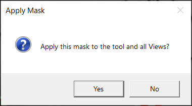
If you click Apply All and click Yes button on the ensuing Apply Mask dialog after adding the necessary masks, the same mask will be applied on all the images. If you click No on the dialog, the mask will not be applied and you go back to the Edit Mask window.
- Press the Close button on the toolbar to continue.
- Go through all of the images and label the images as Good or Bad. Make sure that all of the images have been labeled. See Create Label (Labeling) for the details of labeling.
- Split the entire images into the training images and the test images. Utilize image sets to properly divide them into the training and test group. Add images to the training set.
- Select the images in the View Browser, and on the right-click pop-up menu click Add views to training set. To select multiple images in the View Browser, use the Shift + Left Mouse Button.
- Or, use Display Filters to show the desired images for the training only and add them to the training set by clicking Actions for ... views → Add views to training set.
- Prior to training, you need to set parameters in Tool Parameters. You can configure Training, Sampling, and Perturbation parameters or just use the default values of these. See Configure Tool Parameters for the details of the supported parameters.
- Ensure that the Feature Size parameter has been set. The Feature Size parameter gives the network a clue to the size of the defects that you are interested in detecting. So, if the Feature Size parameter setting is larger than the defects in your application, there is a good chance the tool will not identify the defects in your image.
- You can set the Feature Size by either manually adjusting the parameter value, or graphically by re-sizing the interactive Feature Size graphic.
- If you want more granular control over training or processing, turn on Expert Mode on Help menu to initialize additional parameters in Tool Parameters.
- Train the tool by pressing the Brain
 icon.
icon.- If you stop training in the middle of it by pressing the Stop
 icon, you can stop training but you will lose the current tool so far trained.
- If you stop training in the middle of it by pressing the Stop
-
After training, review the results. Open Database Overview panel and review the Scores/ROC graph, the Confusion Matrix, and its F1 Score with switching over between categories in Count drop-down list. See Interpret Results for the details of interpreting results.
- After reviewing the results, go through all of the images and see how the tool correctly or incorrectly marked the defects in the image.
- If the tool has correctly marked the features, right-click the image and select Accept View.
- If the tool has incorrectly marked the defects, or failed to identify a present defect:
- Right-click the image and select Accept View.
- Right-click the image again and select Clear Markings and Labels.
- Manually label the defective image.
- If you want to tune the result by affecting the processing, you can manipulate Processing parameters and re-process by clicking Magnifier
 icon to get the changed results. For example, to change the decision boundary which is determined by T1 and T2, you can manipulate the Threshold parameter.
 - If you encountered the scenario in (a.), you are ready to use the tool. If you encountered the scenario in (b.), you will need to retrain the tool and repeat the steps 8 ~ 11.
The details of each step are explained in each subsection of Training Red Analyze Focused Unsupervised.